Here is a way to smoothly interpolate (LERP and SLERP) attributes in Maya with just basic nodes, without having to rely on any plugins.
Imagine that you have a smooth or linear curve. And as you animate 2 simple control points, any number of points output their values along that curve, giving you nice twists, blends or falloffs.
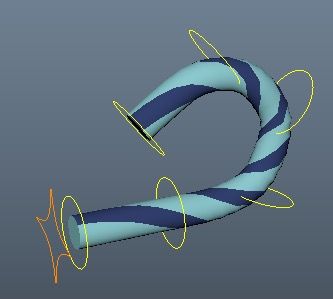
Today's friendly #rigtip will show you how to add a smooth or linear interpolation to your rigs in Autodesk Maya using the versatile remapValue node and a bit of a sneaky workaround! Here are some examples of what this looks like in action. Slerping and lerping translateY, rotateX, and scaling.
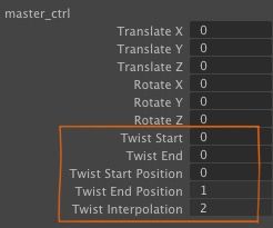
This is animated with only 5 attributes:
Originally, I wrote this because I wanted a replacement for "advanced twist" from Maya's splineIK. I wanted to be able to twist my own custom ribbon IK. Then I realized that this is very useful for a lot of things!
- Twisting a custom ribbon IK or spine or wrist twist in character rigs
- Linear interpolation for mechanical rigging effects
- Smooth interpolation of custom attributes (not just twist)
- Spherical iris/pupil eye scaling
- Getting some procedural-like effects with only a few attributes
How this works
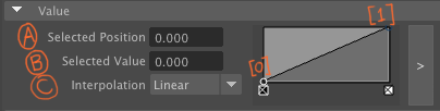
Maya's remapValue node has control points so that you can shape the curve. Each of those control points has an index with the following attributes:
import pymel.core as pm
oMap = pm.createNode('remapValue')
oMap.value[0].value_Position    # (A)
oMap.value[0].value_FloatValue  # (B)
oMap.value[0].value_Interp      # (C)
The interesting thing is that these attributes can be connected to things. So you can drive them with other attributes. Or you can connect multiple remapValue nodes together, so they all act in sync with each other. That's the key to how this technique works, since remapValue only has a single .outValue.
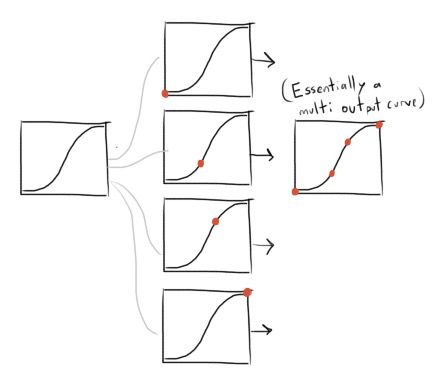
The steps I take to fake a multi-output curve:
(See the Python script and example Maya scene file at the bottom of this article)- Create a "master" remapValue node. This will drive all the others.
- Set the remap .inputMin and .inputMax from 0 to the number of segments you want. Example, 0 to 9 for 10 segments.
- Create 10 copies of the remapValue node.
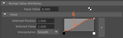
- Each one of those remapValue nodes .inputValue is the index of the segment. 0, 1, 2, 3, 4,... etc.
- This samples a segment point on the curve, and outputs the value at that position on the curve.
- The master remapValue connects to all the others, so when you animate one, they all follow each other.
- Add some attributes to an animation control. To drive the twist, I actually then drive a multiplyDivide node from 0 to 1 to turn it off or on.
- I also use a reverse node in the opposite direction, so I can have both "twist start" and "twist end", and at any point along the curve, those two values always add up to 100%. For example for segment 2, start will influence 2 by 80% and end will influence 2 by 20%. And if you animate start and end at the same time, the entire rig will twist evenly, as if the entire thing was rotating. (If that makes sense.)
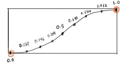
The graph starts by looking something like this:
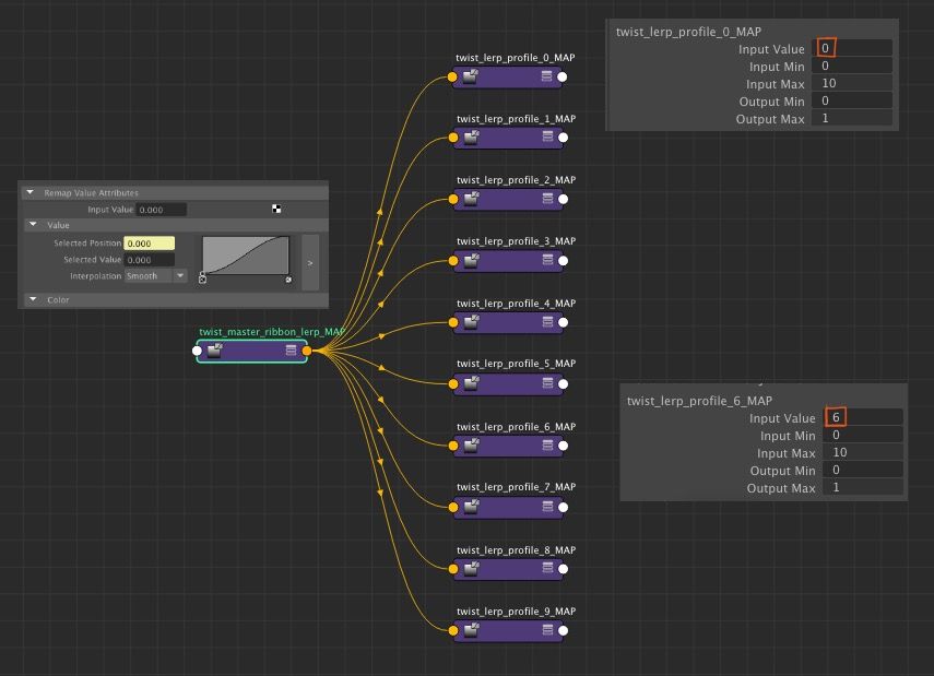
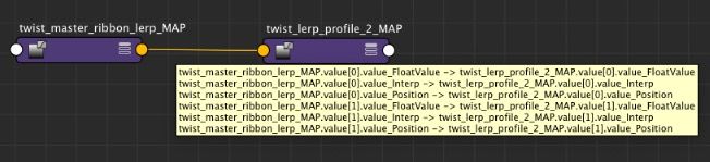
The connections from the master to each segment:
One major limitation
One limitation for this setup is that the control points on the remapValue need to exist when you are setting it up. You can't procedurally add or remove points by editing the curve of the master remapValue. If you wanted to do something like that, you'd need to use some sort of callback, or actually create a plugin with that functionality.
How I used this on my spherical sin/cos eye rig
Now what I really like about this, is that it is generic. It isn't just for twisting. When I rigged my sin/cos eye rig, I used this technique to interpolate all those joints for the pupil and iris scaling.
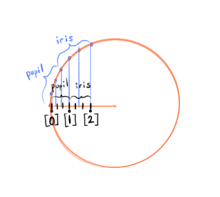
- I used a similar technique, except the remapValue nodes have 3 points:
[0], [1], and [2]` - 0 to 1 is the pupil interpolation. 1 to 2 is the iris.
- I linearly interpolate translateZ in a straight line.
- The linear result of that interpolation drives the sin/cos joints. So the lerp and the final polar result of the sin/cos joints don't perfectly line up, since one is linear and the other is like a polar coordinate along a circle. So the model of my eye geo edge-loops line up with the final result, not with the linear interpolation. (That is what I intended. It's just something to keep in mind, unless you accommodate for that.)
Python Script and Example Scene File
1) Here is a Python script that sets this up automatically. - You specify a prefix such as "twist" for the name of the attributes. You specify the animation control, the collection of objects you want to drive, and the attributes you want to drive. Currently it works on multiple objects. It is not designed to drive multiple attributes on one node, though that would definitely be possible to write.
2) Download an example Maya ribbon rig, to see how this works in action. The main control is the orange diamond "master_ctrl".
Thanks for reading! If you want to get more #rigtips whenever I update the blog, consider signing up below. And if you have any questions or comments, feel free to email or catch me on Twitter.